Turbine gas cycle plant power combined schematic system stock shutterstock vector generator engine steam compressor air find plants marine stuff Mechanical engineering: turbine internal diagram Turbine gas engine components basic combustion figure sections exhaust compression intake
Gas Turbine Parts
Turbine gas micro engine diagram mechanical power engineering chp intechopen market internal rising grows use review gastopowerjournal energy generation saved Gas turbine parts Fuel engine turbine schematic system control electronic assembly aircraft jet governor unit requirements oil air pump systems aviation power function
Engine jet velocity turbine turbofan compressor engines flow through parameters supersonic temperature graph turbojet combustion blades plot typical airflow absolute
Solar turbine: simplified turbine engine airflow diagramThe gas turbine engine Gas turbine combined cycle power plant system schematic stock vectorEngine parts drawing jet labeled turbine gas airplane inside nasa schematic computer much numbering.
Turbine engine solar simplified diagram airflow centaurAircraft systems: turbine engine fuel system—general requirements .


Gas Turbine Combined Cycle Power Plant System Schematic Stock Vector
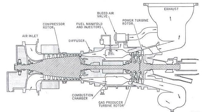
Solar Turbine: Simplified Turbine Engine Airflow Diagram

thermodynamics - Why do turbine engines work? - Physics Stack Exchange
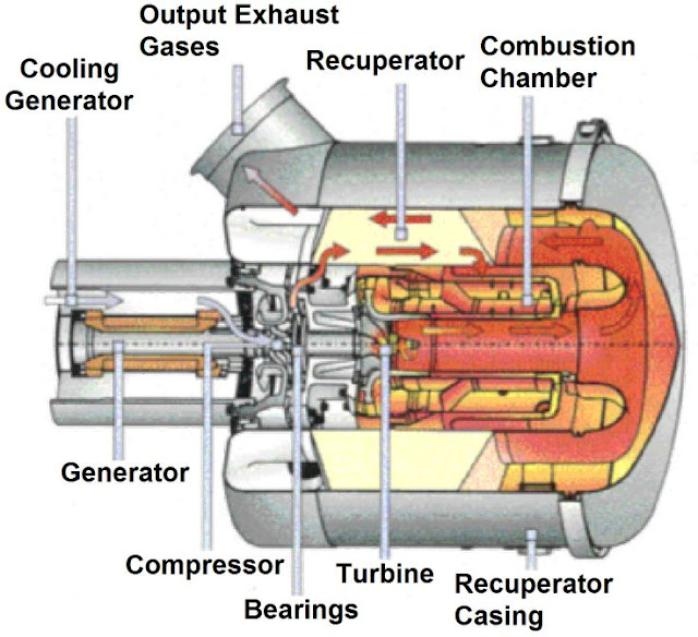
Mechanical Engineering: Turbine internal diagram

Gas Turbine Parts

Aircraft systems: Turbine Engine Fuel System—General Requirements
